Pattern formation in a rotating suspension of non-Brownian particles
W. Robert Matson, Dr. Bruce J. Ackerson and Dr. Penger Tong
Department of Physics, Oklahoma State University
Abstract
Bands and other patterns are observed in a settling suspension of uniform non-Brownian particles in a completely filled horizontal rotating cylinder. A series of sharp pattern changes have been mapped out as a function of the rotation period and solvent viscosity. This simple system displays an amazing richness of flow structures and patterns. For example, the particles can separate into axially periodic band structures in a finite range of rotation rates. These coherent structures are robust, and the characteristic band length and spatial orientation changes less than ten percent over this rotation range. Nine states have been identified, including two transition states where two flow structures coexist. The collective behavior of the particles and their host medium demonstrates new principles in particulate two-phase flows; therefore, progress in this research can touch many areas of applied sciences and engineering. Quantum-dot particles will allow measurement of particle configurations at higher concentrations. This will also allow systematic analysis of local concentration variations and velocity fields for different flow states.
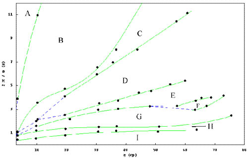
A, Dense particle bed cascade; B, Fingering; C, Finger-Band coexistence; D, Band formation; E, Band loss/Band-rigid body coexistence; F, Asymmetric segregation; G, Rigid body rotation; H, Asymmetric bands; I, Centrifugal dominated collapse.
A, Dense particle bed cascade
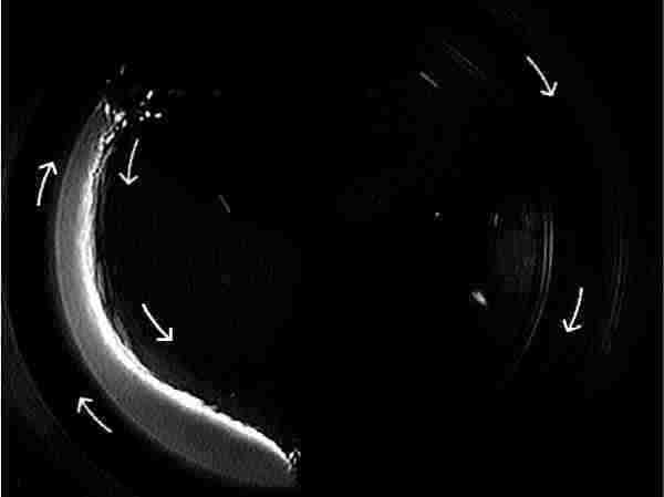
While the particles are carried upward by the rotating wall, their packing density is maximum. Upon reaching a critical angle, gravity pulls them downward through the fluid to the bottom of the cylinder, and their packing density decreases. In the figure above, there is a thin upward moving layer along the wall separated from the larger downward moving region.
B, Fingering
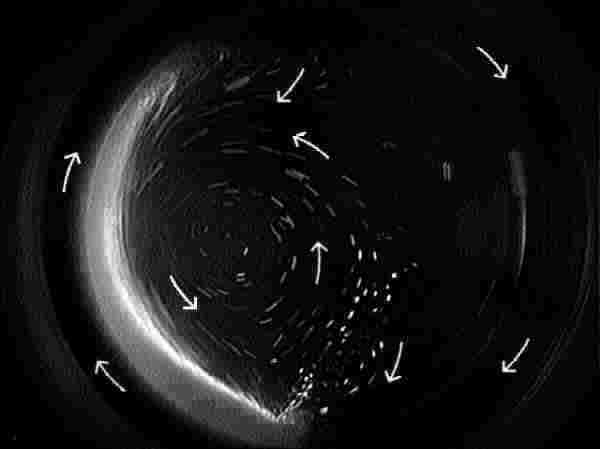
When the granular bed reaches another critical angle, approximately 45?(up from horizontal), the falling sediment begins to separate and form "fingers" as they fall through the fluid. You can see one of these leaving the leading edge of the granular bed in the picture above. These "fingers" fall much faster than the single particles thereby inducing a more pronounced counter-rotation in the fluid. The high shear at the base of the granular bed, where the two flow directions converge, causes particles to be emitted into the counter-rotating fluid. A similar, less compacted convergence region also exists near the top of the cylinder, as evidenced by the streamlines.
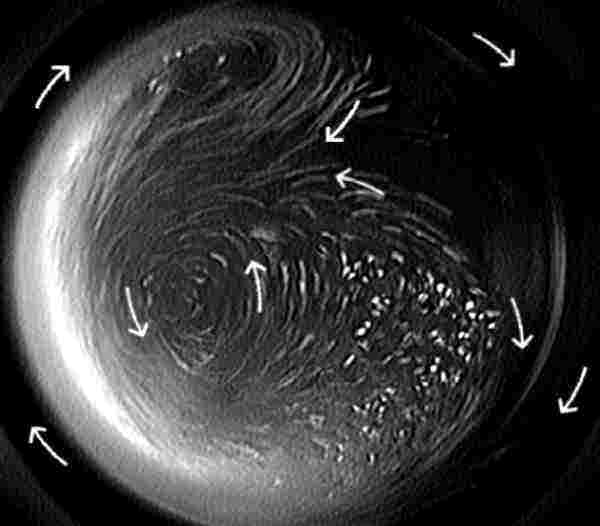
As the rotation rate increases, the fingers grow in width and length as they originate at larger angles from horizontal. The "fingers" fall somewhat parallel to the rising granular bed, as evidenced in the picture above. When the fingers fall near the top of the cylinder (90?, they approach the maximum allowable length as dictated by the cylinder diameter. You can see here the finger does not have a clearly defined start or finish. The particles inside the finger are now falling almost 10 times faster than the individual particles producing a stronger counter-rotating region, higher shear at the bottom, and more particles being introduced into the counter-rotating fluid. As the strength of the counter-rotation increases, the vortices becomes more localized.
C, Finger-band coexistence
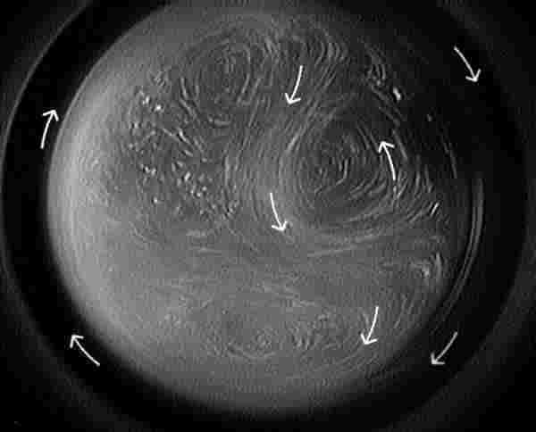
Upon reaching a critical angle > 90? the "fingers" obtain an axial component to their velocity and the flow field becomes three dimensional. In the picture above, there are actually two regions of counter-rotation, one on each side of the "finger," which is now falling near the center of rotation.
D, Band formation

↑

The top picture shows region D in the phase diagram. The bottom picture shows a cross section of the band structure near the region of highest particle concentration. Note the center of circulation is offset from the center of rotation toward the rising side of the cylinder.
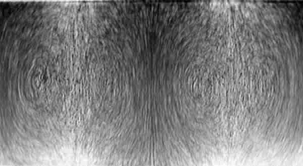
Front view of the circulation profile. Note the symmetry about the concentrated region and the hour-glass shape to the band structure. This shape is characteristic of the band state. The shape remains constant and spacing deviates less than 10% throughout the entire range of rotation rates and viscosities where this state exists.
E, Band loss/band-rigid body coexistence
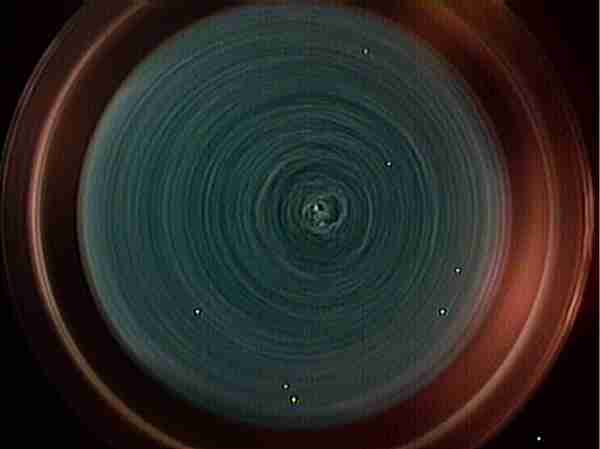
Circulation profile near the void region. Note the center of circulation is not as offset from the center of rotation toward the falling side of the cylinder as it was in the previous pictures.
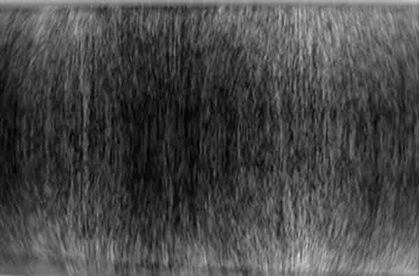
Front view of the decayed circulation profile. Note the symmetry about the concentrated region remains, but the hour-glass shape evident in the band structure has become golf ball shaped in the center of the tube. The outer flow region is becoming more streamlined as a rigid rotation region lines the inner wall of the tube.
F, Rigid body rotation

All secondary flows and sedimentation come to a complete halt and the particles are suspended in the fluid. They reach a uniform distribution and rotate rigidly with the cylinder. This condition is observed to be stable for several weeks without any noticeable change in particle orientation or centrifugation.


G, Asymmetric segregation
Two different tube lengths are shown above in the same state. Note the size of the asymmetric structure is independent of the tube length. The smaller tube appears to be the central slice from the longer tube. Note the "void region" in the shorter tube is now at the end. This pattern is clearly not a form of stratification, as evidenced by the concentration increase on both sides of the "void region" in the longer tube.
H, Asymmetric bands
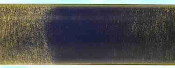
The asymmetric segregation collapses into tightly packed structures as shown above leaving the intervening fluid void of particles (except a few trapped on the cylinder wall). These structures are approximately one centimeter wide. These "bands" are of completely different order than those at the lower rotation rate. The number appearing is dependent on tube length with a ratio of approximately 1 for each 10 cm of length. The spacing between adjacent structures, however, is neither uniform nor symmetric.